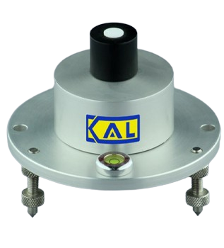
The KDS-051 Solar Radiation Sensor from Komoline uses a high-precision silicon photodiode and cosine-corrected diffuser for accurate global radiation measurement. Its stable, self-calibrating electronics ensure reliable performance with minimal sensitivity to environmental temperature changes. The sensor is designed to be direction insensitive and includes built-in leveling features for easy horizontal alignment, making it ideal for precise solar radiation monitoring in diverse conditions.
Read MoreParameter(KDS-051) | Conditions | Min | Type | Max | Units |
---|---|---|---|---|---|
Radiation | |||||
Type of Sensor | Photo Diode | ||||
Measurement Rang | 0 | 2000 | Wm-2 | ||
Accuracy | 5 | %FS | |||
Resolution | ±1%1 | Wm-2 | |||
Response Time Constant | 0.5 | s | |||
Temperature Dependence | < ±1 | % | |||
Output | |||||
Response Time | 0.5 | s | |||
Settling Time on Power-On | To Rated Accuracy | 5 | s | ||
Latency on Power-On | 1 | s | |||
Update Rate | 0.5 | Hz | |||
Averaging Aperture | User Settable | 0.5 | 600 | s | |
Physical | |||||
Mass | Cable Not Included | <400 | g | ||
Size | 120 x 120 x 120 | mm | |||
Enclosure Materials | Anodized AI6061/Acetal/SS316L | ||||
Cable | UV Resistant Cable | ||||
Deployment | |||||
Location | Outdoor | ||||
Operating Temperature Range | -40 | +60 | °C | ||
External Interface | |||||
The sensor is available in nine standard output configurations as detailed below |
Output Option | Interface | Leve | Baud Rate | Protocols | Max Cable Length | Power Supply |
---|---|---|---|---|---|---|
3V Digital (D00) | UART | 3V Digita | 9600-115.2k | KomBus/Modbus | 5 to 10m | 4-28V (<1mA) |
RS485 (D01) | UART | RS485 | 9600-115.2k | KomBus/Modbus | 250m | 4-28V (<1.5mA) |
RS232 (D02) | UART | RS232 | 9600-115.2k | KomBus/Modbus | 10m | 4-28V (<1.5mA) |
Voltage Output 1 (A01) | Voltage | 0-1 to 0-3V | – | – | 10 to 20m | 4-30V (1.5mA) |
Current Loop (4-20mA) (A02) | Current | 4-20mA | – | – | 250m | 4-40V (4-20mA) |
Voltage Output 2 (A03) | Voltage | 0-3 to 0-10V | – | – | 20 to 40m | 4-30V (<2.5mA) |
Radio 1 (R01) | Radio | 433 MHz | 9600-115.2k | Please See User Manual for Details | Please See User Manual for Details | Internally Lithium Powered |
Radio 2 (R02) | Radio | 930 MHz | 9600-115.2k | |||
Radio 3 (R03) | Radio | 2400 MHz | 9600-115.2k | |||
Calibration | ||||||
Calibration Facility | KAL Sensor Calibration Facility | |||||
Traceability | IMD (India) / NPL (India) / NIST (USA) | |||||
Accessories | ||||||
Included with Sensor | Mounting Accessories, Readout and Setup Software (for Windows), Mating Connector (Wired Versions), 10m Sensor Cable | |||||
To Be Separately Ordered | Extra Cable, Readout. Connectivity Adaptor for USB, RS232, Radio etc | |||||
Notes. 1.Accuracy is specified with one minute or more averaging, at 25°C, after full calibration. 2. Output units can be customized if required. Please contact factory. 3. Response Time is the time the sensor takes to capture 90% or more of a step change with the averaging set to minimum. 4. Temperature measurement accuracy about 3 deg. C. 5. Analog output offered can be set by the user to cover any interval within the sensor’s range. 6. Does not include current sunk by the host system out of the sensor’s output lines and is valid for digital operation only. 7. Supply Voltage must exceed the required voltage compliance by 1 Volt at least. |
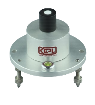
The KDS-053 Light Intensity Sensor from KAL is designed for precise measurement applications and features RS485 connectivity for long-distance communication. It features multi-drop configuration, advanced microcontroller-based architecture and embedded calibration routines for reliable and consistent performance; and offers compatibility across different sensor types.
Read MoreParameter KDS-053 – | Conditions | Min | Type | Max | Units |
---|---|---|---|---|---|
The Sensing Front End | |||||
Type of Sensor | Precision Silicon Photodiode | ||||
Type of Sensing Element | High Stability Electronics | ||||
Type of Optical Interface | Cosine-Corrected Diffuser | ||||
Sensing Area | 80 | mm2 | |||
Spectral Response | 10% Points | 380 | 800 | Nm | |
Field of view | Cosine Corrected Incidence Range | -60 | +60 | ° | |
Ful | 170+ | ° | |||
Averaging Aperture | User settable | 1 | 600 | s | |
Totalization | User Resettable | Available | |||
Measurement | |||||
Measured Parameter | Light Intensity | ||||
Spectral Reference | Standard Solar Spectrum | ||||
Accuracy | At calibration point | 2 | % FS | ||
Full Range | 4 | % FS | |||
Resolution | 10 | lux | |||
Long-Term Stability | 1 | %FS | |||
Dark Reading | 0 | lux | |||
Power Supply | |||||
Supply Voltage | Line Drop Not Included | 4 | 12 | 28 | V |
Reverse Polarity Protection | 28V, Indefinite Time | ||||
Current Consumption | <5 | mA | |||
Output | |||||
Type of Connectivity | RS485, Half-Duplex | ||||
Number of Wires | 4 (Supply Voltage, RS485-A, RS485-B, Ground) | ||||
Type of Communication | UART | ||||
UART Setup | 9600 Baud, No Parity, 1 Start Bit, 2 Stop Bits | ||||
Communication Protocol | KomBus 1.0 | ||||
Deployment | |||||
Deployment | Outdoor, Continuous | ||||
Mounting | On Base Plate / Level Hard Smooth Surface | ||||
Cable Length | 250 | m | |||
This cable length is the rated maximum drive capability of the sensor. The standard issue of cable is 10m, extendable upon request. | |||||
Environmental | |||||
Operational Temperature | Ambient | -40 | +60 | °C | |
Storage Temperature | -40 | +80 | °C | ||
Humidity | Condensation Tolerant | 0 | 100 | %RH | |
Rain | Fully tolerant to tropical rain | ||||
Mechanical | |||||
Maximum Dimensions | 125 x 125 x 125 mm | ||||
Leveling | Spirit Level Assisted Leveling Screws | ||||
Mass | Cable Not Included | <400 gm |
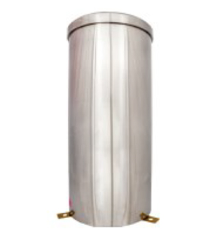
KDS-071 Tipping Bucket Rain Sensor by Komoline Aerospace is a rain measurement sensor employing a reliable tipping bucket mechanism and advanced electronics. It features a high-precision bucket with a WMO-recommended 200cm2 collector area and knife-edged rim for precise calibration, ensuring accurate rain rate output under diverse weather conditions.
Read MoreParameter KDS-071 – | Conditions | Min | Type | Max | Units |
---|---|---|---|---|---|
Rain Measurement | |||||
Type of Sensor | Rugged Magnetic Proximity Reed Switch Pickup / Tipping Bucket with hall effect | ||||
Measurement Range | Unlimited | ||||
Accuracy | ±2% for rain rate up to 25 mm/hr | ||||
±3% for rain rate between 25 mm/hr to 50 mm/hr | |||||
±4% for rain rate between 50 mm/hr to 100 mm/hr | |||||
±5% for rain rate above 100 mm/hr | |||||
Resolution | Options Available | 0.1/0.2/0.25/0.5 | mm Rain | ||
Response Time Constant | 0.1 | Seconds | |||
Collector Area | 200 | cm2 | |||
Collector Diameter | 159.6 | mm | |||
Output | |||||
Reed Switch Electrical Characteristics | Potential Free Contact | ||||
Reed Switch Closure Pulse Width | 10 | 100 | |||
Reed Switch Breaking Voltage | 100 | ||||
Reed Switch Breaking Current | 250 | ||||
Physical | |||||
Mass | >2.3 | kg | |||
Size | 210 Ø(Base), 174(Body), 410(Height) | mm | |||
Cable | 2 Core Sensor | ||||
Construction Materials | |||||
Rain Collector | UV Stabilizer, Fiber Embedded Plastic | ||||
Collector Area Stabilizer | Gunmetal (Brass Alloy) | ||||
Internal Parts | Engineering Plastic, SS316L, Chrome Planet Brass | ||||
Material of Outer Body | Stainless steel / Aluminium | ||||
Deployment | |||||
Location | Outdoor | ||||
Operating Temperature Range | -40 | +85 | °C | ||
Leveling | Level Adjustment Screw and circular spirit level for leveling of Tipping Bucket Mechanism |
Output | Switch Closure Time | Max Cable Length |
---|---|---|
Potential Free Contact | 0.1 Sec | 10 meter Two Core shielded copper cable |
Mounting Accessories | 1 ft x 1 ft square Plate (Material: Galvanized iron or Zinc Passivated iron) | |
2 ft Galvanized iron pole of suitable dimensions and sufficiently strong for TBRG installation | ||
Calibration | ||
Calibration Facility | KAL Sensor Calibration Facility | |
Traceability Offered | IMD (India) / NPL (India) / NIST (USA) | |
Accessories | ||
To Be Separately Ordered | Extra Cable, Read out, Connectivity Adapter for USB R232, Radio etc | |
Notes. 1. The product is available with and without electronics. 2. An internal Voltage/Current output engine is available which can be programmed to output a voltage or current proportional to the normalized value of the rain accumulator with user’s full-scale value. 3. Externally sunk current not included. This current is the load on the bus supply; the unit remains functional without any external power on its internal lithium power source. |